Download the library package (zip) from the link given at the end of this page and extract and copy all the files to the following location
Program Files (x86)\Labcenter Electronics\Proteus 7 Professional\LIBRARY
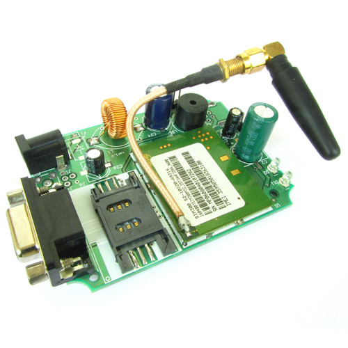
to add SIM900 to your schematic, start ISIS, goto component mode and click pick from library. This will open up the window as shown below.

Type SIM900 in the search box, and then double click SIM900 on the list on right side. This will place SIM900 in your project.
In the same way put
- SMA (antenna connector)
- SIM_CARD (sim card holder)
Now you can place them in the schematic sheet and shown below.

After interconnection click the ARES button (Last RED button in the toolbar), this will take you to PCB design. Define a board edge and then start placing and routing the tracks.

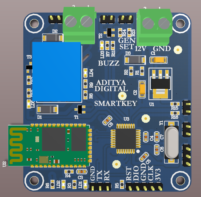
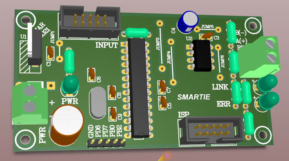
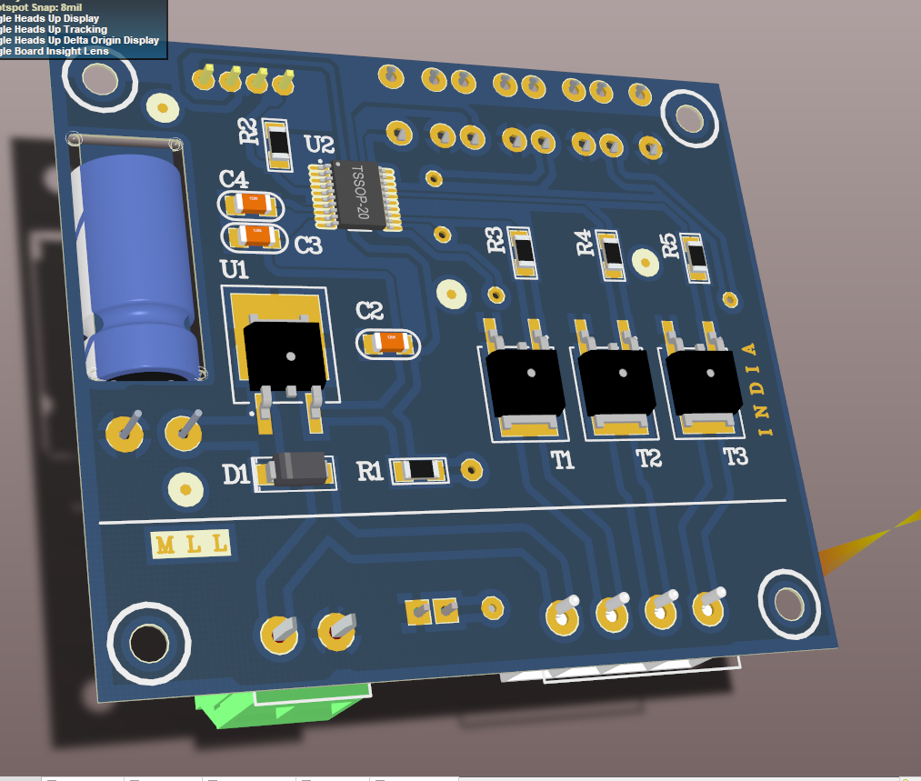
You can now goto menu Output > 3D Visualization to see the 3D preview of the design.

We cordially thanks the following peoples who shared this page on various social networks and insprided us to develop more quality contents!
Kumar, Hamed, Yy, Swapon, Chuc, Maurice Yelfaanibe, Kien, JONH, Nassym, Do Truong Giang, Eliomar, Avinash Gupta,


