Most of you must have watched quiz games in TV shows or at your schools where few contestants are required to press a switch if they know the answer to the question. An electronic system is required to find out exactly which one of then pressed the button first. This type of electronic system can be easily designed with an AVR microcontroller like ATmega16. We will make a system that will support upto 8 contestants so we will need eight inputs. These inputs are switches that would be placed on each contestant's table. We also need eight outputs, these will be the indicator lights put on the tables. These will indicate which one of them pushed the button first. Since we are using a programmable IC we will make this more fancy by adding a blinking effect to these lamps. So they will not simply glow as in other projects but also they will blink to attract attention!
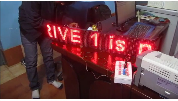
To make this even fancier, we will also add a seven segment display to numerically show the id of contestant who pressed the button first. We will be using a 4 inch display that runs off 12v so we need a ULN2003 to drive them.
We also have a buzzer in this system which beeps when any button is pressed. To use the system next time, reset button must be pressed.
Circuit Diagram

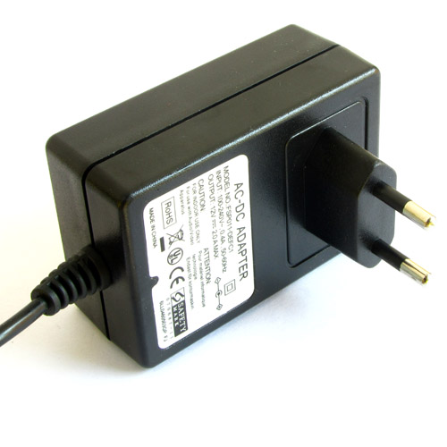
The power supply units takes input from a 12V DC adapter and convert it to 5v supply for microcontroller and other ics. Diode D9 prevents burning of 7805 ic from reverse voltage. Capacitor C1 filters ripple from power supply, IC7805 is the voltage regulator IC. Diode D10 is the power indicator LED and R3 limits the current to it. R2 keeps the RESET pin of MCU pulled up for normal operation while RESET push button can be used to reset the MCU.
R1, Q1 forms the driver circuit for the buzzer. IC ULN2003 is used to drive the large seven segment module.
330 ohms resistors should be used in series with the output leds. These resistors are not shown in the schematic.
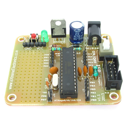
This circuit can be made in a general purpose PCB or a Basic PCB for ATmega16.
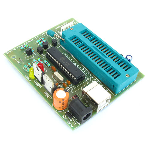
ATmega16 should be programmed with the HEX file given at the end of this article, the HEX file contains the program in machine language and is burned to the flash memory of ATmega16 using USB AVR Programmer.
After burning the program, configuration of ATmega16 should also be done. This step is often ignored by many users and that results in failure of the project. Their are many setting of the MCU those are required to be adjusted for specific projects. For example in this project we need to use the internal oscillator 1MHz of ATmega16. While ATmega16 supports following oscillator too
- Internal RC
- External RC
- External Clock
- External Crystal
We also need to disable JTAG debugging because we don't need them. By default JTAG is enabled and PC2,PC3,PC4,PC5 are used for JTAG connection and these will not function as regular IO port and LEDs connected to them will not glow.
These configuration can be done by programming proper values in the fuse bytes. The low fuse byte should be set to E1 and high to D9 these can be done by going to Fuse Bits/Setting tab of eXtreme Burner AVR and entering the values and clicking Write button.

Now the ATmega16 chip is fully ready to be mounted on the circuit.
We cordially thanks the following peoples who shared this page on various social networks and insprided us to develop more quality contents!
????, Avinash,