In this article, we will discuss the complete process of generating sine wave signals from a digital microcontroller. Since the output port of microcontroller can output only 0 and 1 that means 0v and 5v states only. So first we need a way to generate analog output i.e. any voltage level between 0v and 5v, say 3.75v or 1.23v or 0.33v . This would be done using PWM output of the microcontroller and a low pass RC filter.
For basic information on PWM please read this article.
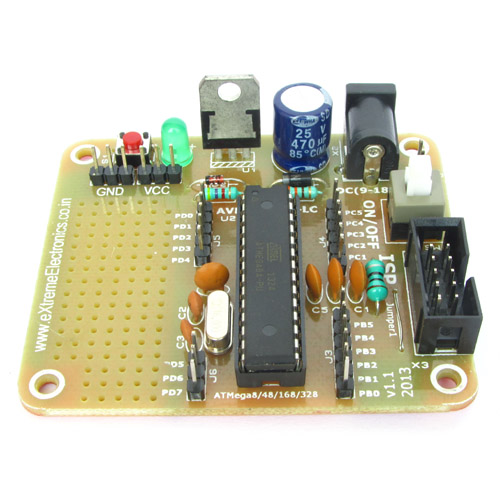
For PWM generation we will use TIMER1 of ATmega8, we will use the Phase and Frequency Correct Mode. This is mode 8 of the timer. Refer page 99 of the datasheet.

We will keep resolution of this PWM 8 bit. So that it can divide the available voltage range of 5v into 255 divisions. That means we can control output voltages in steps of 0.0196 volts. That is pretty good!
The PWM signal will be available in OCR1A pin of the microcontroller. But still it is digital, only the duty cycle is varied to effective lower voltage levels. We need a low pass RC filter to convert it into a pure analog voltage. We have designed a low pass filter with a cutoff frequency of about 2200Hz and attached it to the output from the microcontroller.

Now that we have got the whole setup to generate analog voltage from a digital microcontroller who never knew beyond 0's and 1's, its time to periodically generate output voltages according to a mathematical function called sine.
y=sin(x)
where x is angle in radian, in a whole circle their are 2 pi radians. That means x varies from 0 to 2 pi or 2 x 3.14 (value of PI is 3.14) = 6.28
Also the result of sin may be negative too. To handle this situation we have moved the 0 point to the mid point of the PWM that is 255/2=127, so anything negative will go below 127 and anything positive will be above 127. Therefore, actually 127 will be 0 for us.
One more thing, the output of sin function varies only from -1 to +1, so we need to scale this value by multiplying it with 127.
Final equation will look something like this
y=127+(127*sin(x));
we divide the whole sine wave into hundred equal parts, and store their value in a table (array in C)
 x=0;
for(i=0;i<100;i++)
{
	sine[i]=127+(127*sin(x));
	x=x+0.0628; //in whole  circle their are 6.28 radians, this is 1/100th part of it
}
Actually I have written a small program in PHP to generate this sine table for me. Now in the AVR microcontroller our task is to read values from the sine table and output them to the PWM at regular intervals. Calculation of that interval and setting up the TIMER0 to fire interrupt at that interval is our next task.

We cordially thanks the following peoples who shared this page on various social networks and insprided us to develop more quality contents!
Ghemog, Rana, Mojtaba Rahmani, Student, Ali Jahan, Abbassa15, Ragab Ali, Md Abul Kalam, Maghsoud Ahmadi Anvar, Fawzy, Hadi, HoangThanhTam, George, Avinash Gupta,