Capacitors are two terminal electronic component used to store energy in form of electrostatic field. They are one of the most commonly used components. Among the many uses, some are :-
- Providing a bypass path for noise
- Smoothing voltage of power supply
- Blocking DC current (allowing only AC current to flow)
The capacitor's ability to store charge is called capacitance and is measured in units of Farad (symbol: F).
F is a very big unit, so practically smaller units are used.
pF or Pico Farad = 10-12F (0.000000000001 F)
nF or Nano Farad = 10-9F (0.000000001 F)
uF or Micro Farad = 10-6F (0.000001 F)
How capacitors look like?
Primarily, capacitors (like any other electronic parts) can be divided into two types depending on the way they are mounted on PCBs.
- Through hole type (bigger, but easier for prototype assembly)
- Surface mount type (SMT, smaller, good for mass production)
in this article we will cover only the through hole type.
So now let's see how do they look like. Since the look depends on type and specifications, it is not possible to provide a single image. But we have tried to collect the all common types.
 |
| Fig. Capacitors of various types |
Their are several types of capacitors, but to keep tutorial simple we will discuss only about the two most common types used in low voltage circuits. They are :-
- Electrolytic type (they are polarised, that means one of the lead is positive and another is negative)
- Ceramic disk type (they are non-polarised, that means both the leads are equivalent)
From the image above you can notice the following about electrolytic capacitors.
- They have two leads made of metal.
- One of the lead is longer than the other.
- They have cylindrical shaped body.
- Their body colour is blue or orange (but this can vary and depends on manufacturer)
- Their capacitance is marked on their body.
- Their size increases with their capacitance.
Beside their capacitance, their is one more parameter associated with a capacitor. This is the maxim potential difference (in volts) that can be safely applied across its leads. It is also marked in the body. Size of capacitor increases with this voltage rating. For example in the image above, both the capacitors on the left are 470uF only but the one on the extreme left is bigger only because it is rated at 63v while the other is rated at 25v.
The capacitance of electrolytic capacitors are generally higher (in comparison to ceramic type). Normally they are available from 0.47uF to about 10,000uF
From the image above you can notice the following about ceramic capacitors.
- They have two leads made of metal.
- Both the leads are of same length.
- They have circular shaped body.
- They are light brown in colour.
- Their capacitance is marked on their body. But it is in form of a code which discussed latter.
- Their size increases with their capacitance.
The capacitance of ceramic capacitors are generally lower (in comparison to electrolytic type). Normally they are available from 10pF to about 1,00,000pF (equivalent to 100nF or 0.1uF)
Soldering Electrolytic Capacitors
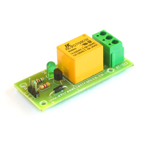
On a printed circuit board, an outline pattern is drawn to help you correctly mount a electrolytic capacitor. See the image given below.
 |
| Fig. PCB land pattern for capacitor. |
It is clear from the image that it has two holes on the either sides to insert the legs of a capacitors. The legs of capacitor are inserted into the PCB holes. Then they are soldered on the other sides to make their legs connected with the circuit. Finally excess part of the metallic legs are cut off by a nipper.
 |
| Fig. Soldering Capacitors |
Soldering Ceramic Capacitors
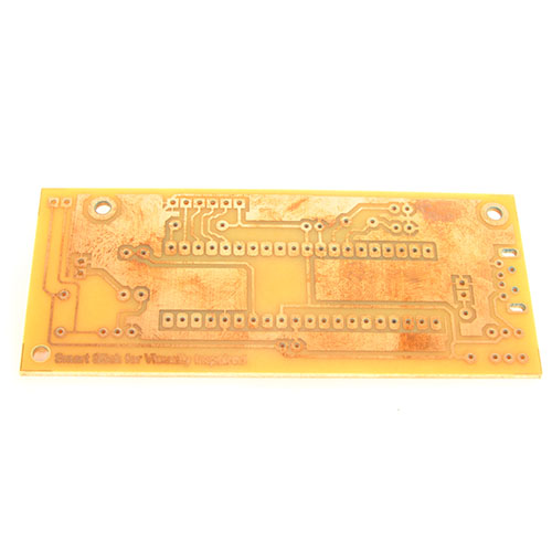
The PCB outline drawings for ceramic capacitors are shown in the image given below.
 |
| Fig. PCB Outline drawing for ceramic capacitors |
Their is no difference between the two pins of ceramic capacitor, so you can insert them in the either way.
 |
| Fig. Soldering Ceramic Capacitors |
Schematic Symbol for Capacitors
 |
| Fig. Ceramic Capacitor Symbol |
 |
| Fig. Electrolytic Capacitor Symbol |
We cordially thanks the following peoples who shared this page on various social networks and insprided us to develop more quality contents!
Swapnil, Mounika Mandapalli, Raja, Adil, Nuruddin A. Syed,