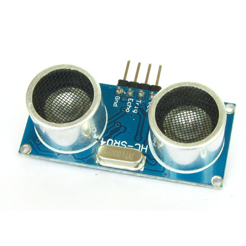
For sensing distance to obstacles, an HC-SR04 sensor module is a great choice. It can give you accurate distance to any obstacle in front of it. This can be used in several projects including high end robotics.
It has an ultrasonic transducer which generates the ultra sonic waves, an ultra sonic receiver and control circuitry built on a small PCB.

Front View of HC-SR04

Back View of HC-SR04
For interfacing with microcontroller it provides two lines namely TRIGGER and ECHO. The trigger pin is an input pin, the MCU sends a 10uS high pulse on this line to tell the HC-SR04 to start a taking a measurement.

As soon as the HC-SR04 receives this pulse it sends out ultrasonic waves and waits for it to goto the obstacle and come back to the sensor. The sensor then emits a pulse on the ECHO line whose width is equal to this time. By simple calculation we can find the distance to obstacle.

Programming
All the programs available in this site is wriiten in C language. For PIC series of microcontrollers I always use the XC8 compiler from microchip. It it available free of charge from them!
To make to program configurable easily, i start off by defining constant for the PORT where we will connect our sensor. So that the user is free to connect the sensor on different i/o port and change the program to adapt is change easily.
#define US_PORT PORTA
#define US_TRIS TRISA

#define US_TRIG_POS  0
#define US_ECHO_POS  1
So now we will refer to the port where the sensor is connected as US_PORT (US stands for ultra sonic). We have also defined the position where the TRIG and ECHO pins are connected. So TRIG is connected to PORTA bit 0 or RA0 in short. In the same way ECHO is connected to RA1 of the PIC16F877A chip.
Then we also define a couple of constant for errors related to sensor.
#define US_ERROR     				-1
#define US_NO_OBSTACLE          	-2
We then define our first function to initialise the system. The initialisation is super simple. Just we need to set the direction of TRIG pin as out (that means RA0). By default all pins of microcontroller are input only, so we do NOT need to set the direction of ECHO pin, as we want it to be input type only.
void HCSR04Init()
{
   US_TRIS&=~(1<<US_TRIG_POS);
}
Problem understanding the above? Then you need basic knowledge about how i/o ports work in PIC16F series. Please see the articles given below for more information ...
- General purpose input output ports of PIC microcontrollers.
- Setting and Clearing bits in a register.
We have simply cleared the bit denoted by US_TRIG_POS (that is 0) in the register US_TRIS. US_TRIS is alias for TRISA. Every i/o port in PIC MCU has a assoiated TRIS register that is used to set the direction (input or output) of each individal pin in the port.
Triggering the HS-SR04 Sensor
The next step is to develop a function to trigger the sensor. That means to send a pulse of 10uS (micro second) to the TRIG pin. This is done by the following function.
void HCSR04Trigger()
{
   //Send a 10uS pulse on trigger line
   US_PORT|=(1<<US_TRIG_POS); //high

        __delay_us(15);       //wait 15uS

   US_PORT&=~(1<<US_TRIG_POS);   //low
}
This function simply makes the TRIG pin high, then wait for 15uS and then makes this pin low.
Measuring the Width of Echo Pulse from the Sensor
This is the most complex and challanging task of the whole project. You need to precicly plan this part. I have used TIMER1 to measure the time.
- Wait for a rising edge on ECHO line. If edge is found start the timer, else if we have waited to long and seen no edge coming end the function and return error code.
- Now the timer is counting in micro second, we wait for the falling edge. As soon as we get a falling edge, stop the timer and return the time elapsed to the calling function. If we waited to long and seen no falling edge that means their are no obstacle in front of the sensor so return an error code.
int16_t GetPulseWidth()
{
   uint32_t i,result;

   //Wait for the rising edge
   for(i=0;i<600000;i++)
   {
      if(!(US_PORT & (1<<US_ECHO_POS)))
                    continue; //Line is still low, so wait
      else
                    break; //High edge detected, so break.
   }

   if(i==600000)
            return US_ERROR;  //Indicates time out

   //Rising Edge Found

   //Setup Timer1
   T1CKPS0=1;  //Prescaller = 1:2
   TMR1=0x00;  //Init counter
   TMR1ON=1;   //Stat timer

   //Now wait for the falling edge
   for(i=0;i<600000;i++)
   {
      if(US_PORT & (1<<US_ECHO_POS))
      {
         if(TMR1 > 60000) break; else continue;
      }
      else
                    break;
   }

   if(i==600000)
            return US_NO_OBSTACLE;  //Indicates time out

   //Falling edge found
   result=TMR1;

   //Stop Timer
   TMR1ON=0;

   if(result > 60000)
            return US_NO_OBSTACLE;  //No obstacle
   else
            return (result * 0.4);  // since period of timer is 0.4uS
}
Calculating distance from Time
Now this function is returning the length of the pulse in microsecond (uS). Its time to convert this to cm. For this we have to refresh our knowledge of Kinematics and recall the relationship of speed, time and distance.
We know that speed = distance traveled / time required to travel the distance.
So
distance = speed x time (simple maths!) Eq. 1
And since actual distance to obstacle is only half of the distance traveled by sound
Distance to obstacle = (speed x time)/2 Eq. 2
Speed of sound in air is
34359cm/sec = 0.034359cm/uS
substituting this value in equation 2 we get
Distance to obstacle = (0.034359 x time) /2
or
Distance to obstacle = (0.01718 x time)
So whenever we require the distance, we multiply time as returned by GetPulseWidth() function by 0.01718
Complete Demo Program
Now we have the distance calculated, but how we are gonna view that? In order to provide a complete demo of the theories taught above. We will create a simple program that will display this reading on the LCD Module. For this the project will also need support of our LCD library.
Hardware
To run this demo you need a PIC 16F877A based development board with LCD module, you can buy it from the link. It has built in LCD mdoule so you don't need to care much about its connecting. Your job is very simple, just to connect four pins of the HC-SR04 sensor to the development board. For that you need single pin female/female burg wires.
| HC-SR04 | Dev Board |
|---|---|
| VCC | 5V OUT |
| GND | GND (0V) |
| TRIG | RA0 |
| ECHO | RA1 |

We cordially thanks the following peoples who shared this page on various social networks and insprided us to develop more quality contents!
Subbuvairam, Gemgem, Ultra, MDF, , Lamrrales33, Jaguar601021, Muhammad Syafiq Ab Aziz, Priti, Brand, Azmi, Sridevi, HERMANN, Lorenzo, Bharathesh, QAMAR SHAIKH, Anurag Bisht, Avinash Home FF,