This counter system built using AVR ATmega16 can be used to count objects passing in a converyer belt or peoples entering of leaving a room. It is bidirectional, that means if a person enter the room, it will increment the count and if a person leaves the room then it will decrement the counter. The count is displayed in a 3 digit seven segment display.
Object or visitor is sensed using IR sensors. On one side we place an IR led that emits invisible IR rays. These rays are incident on ir sensors placed on the opposite side. When IR rays are freely falling on the sensors, the output of the sensor is LOW (that is close to 0v) and when any obstacle comes between the IR LEDs and the sensors, the rays cannot reach the sensor, thus making the output of IR sensor go HIGH(close to 5v).
The output from the IR sensor is connected to analog to digital converter of ATmega16. ATmega16 has 8 channel ADC but only two channels ADC0 and ADC1 are used for two IR sensors. For more information on ADC please refer to this article.

Circuit Diagram
I have split the circuit diagram in three different parts for easy understanding. The first part is given below. It show the power supply unit and ATmega16 base unit. To this unit we connect the display unit and sensor unit.

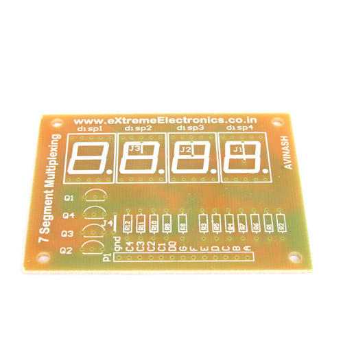
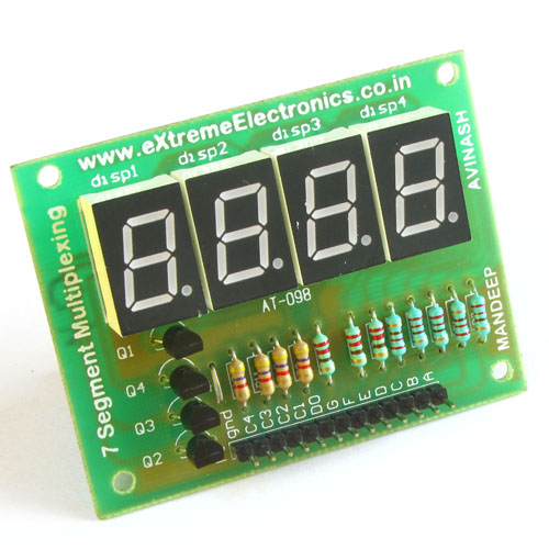
The second part details the display unit, which is made up of segment displays. This part is connected to above circuit where it is labeled "TO SCHEMATIC 2"

Schematic 2
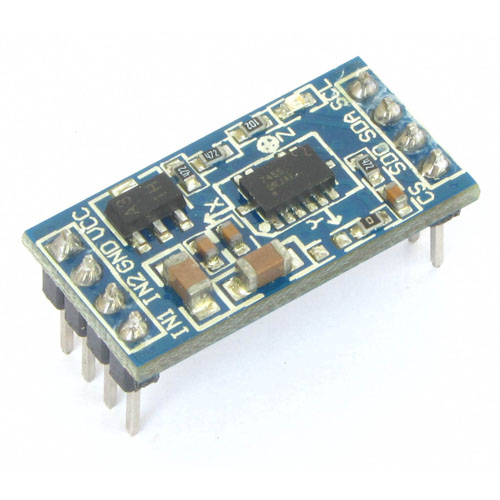
Finally we come to the third part which is the sensor part. This part is fairly simple. We use ready made modules from eXtreme Electronics. The IR led part has only two pins, you should just feed it 5v to make it work. This 5v can be easily taken from schematic 1.
IR receiver part has three pins, two of it are used to power the module in the same way as the discussed above. The third pin should be connected to ADC pin of ATmega16. Two such IR receivers are used, so the output from first sensor is feed to ADC0 while output of second is feed to ADC1. In the schematic shown below the power capacity of R3 (that is the resistor which is in series with the IR LED) should be 1 watt. Rest all resistors are 1/4 watt. D1 is an IR led which can be purchased from the link. U1 and U2 are IR photo transistors which can be purchased from here.
You can also buy complete assembled PCBs of the IR transmitter and receiver from this link.

Schematic 3
This completes our circuit.
Below I am giving the pinout of seven segment display so you do not face any problem while wiring it.

Since this is a microcontroller based project. The major functioning of the project is defined in software. By software I mean a small program. This program runs on the microcontroller i.e. ATmega16 in this case. A microcontroller is a very small single chip computer that has a CPU, RAM, Flash and a set of peripherals. All these makes it complete to execute a set of instructions step by step. This set of instruction is stored in binary form in the FLASH memory of the microcontroller. It has RAM which is used to store temporary data and variables.
Program is developed using a programming language like C. So you need complete knowledge and experience of C programming. You need compilers and development environments installed on your PC to develop program for AVR series. Please refer to the following link for the details of the steps.
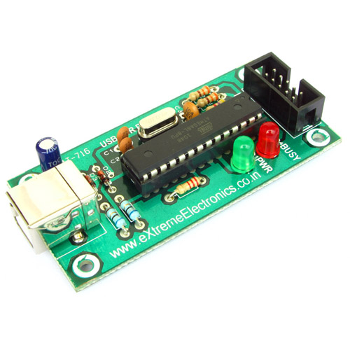
After the programmer completes the development process and create a program that is working as expected, final HEX file that contains the program in language that AVR series microcontroller can understand is generated and is ready for distribution. The user who wishes to develop this project can download this HEX and then burn it to ATmega16 using a USB AVR Programmer.
After burning the program, configuration of ATmega16 should also be done. This step is often ignored by many users and that results in failure of the project. Their are many setting of the MCU those are required to be adjusted for specific projects. For example in this project we need to use the External Crystal Oscillator. While ATmega16 supports following oscillator too
- Internal RC (No external components required, lowest cost solution but not accurate timing)
- External RC (An external resistor and capacitor used as oscillator)
- External Clock (If you have another MCU in the same project, output from that MCU is used as clock source, so single crystal can run multiple MCUs)
We also need to disable JTAG debugging because we don't need it. By default JTAG is enabled and PC2,PC3,PC4,PC5 are used for JTAG connection and these will not function as regular IO port and LEDs connected to them will not glow.
These configuration can be done by programming proper values in the fuse bytes. The low fuse byte should be set to FF and high to C9 these can be done by going to Fuse Bits/Setting tab of eXtreme Burner AVR and entering the values and clicking Write button.

Now the ATmega16 chip is fully ready to be mounted on the circuit.
Video
We cordially thanks the following peoples who shared this page on various social networks and insprided us to develop more quality contents!
Rachid, KULDEEP, Muthiah Kudiarasu Gandhi, Shamini, Fernando, Azdin, Iing, Vaibhav Mishra, Samir Khan, Mayomikun, Tory, Sanju, Pawan, Hashim, Mahak Varshney, Adil Elsadiq, Firdaus, Amar, Avinash,