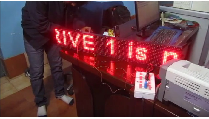
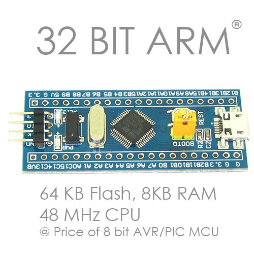
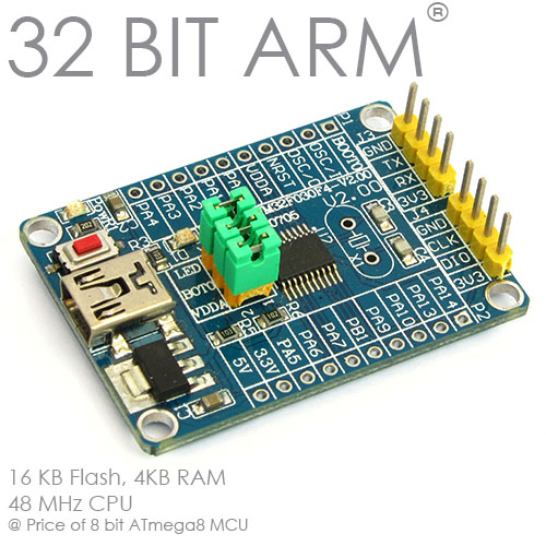
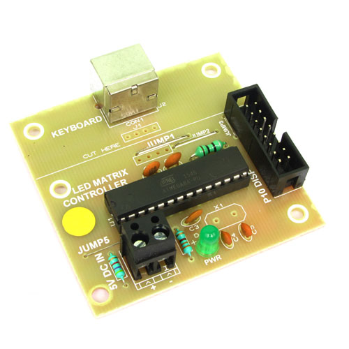
In this article I will share my code for interfacing a 32x16 pixel P10 dot matrix LED display that has dual colour LED for each pixel. These two colours are RED and GREEN. If you turn on both the LEDs of each pixel at the same time, we will get YELLOW colour. So in this way this panel is actually a tri colour display. This is a more advance version of the single colour P10 display. I have used STM32F030F4 microcontroller for this project. It is a ARM Cortex M0 32bit microcontroller which runs at 48MHz and has 16KB flash and has 4KB SRAM. It is available in 20 pin TSSOP package.
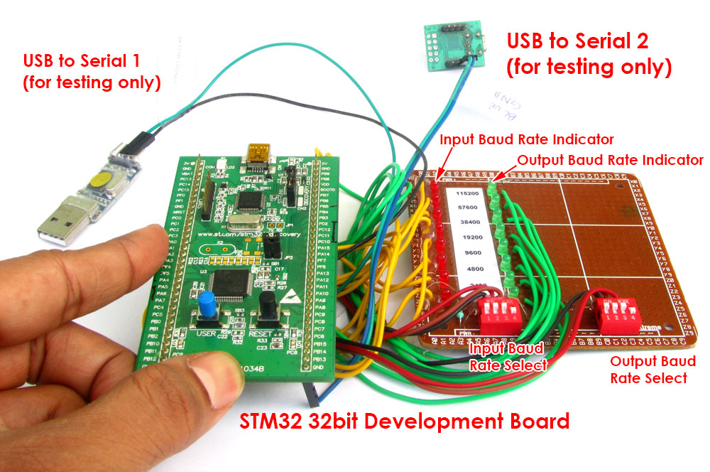
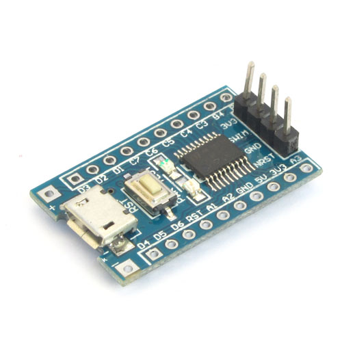
For this project I have used a small development board that has the chip presoldered, it also has a 3.3 volt regulator builtin, this enables me to feed 5v from SMPS directly to this board. The image below shows the connection details of this board with a P10 RG panel.


In the image above you can see that 5v to SMT32F030F4 board is given from USB cable connected to PC. But you can also provide the 5v from the same SMPS that supplies the P10 module.
The software has been written in C and compiled using KEIL MDK ARM.
We cordially thanks the following peoples who shared this page on various social networks and insprided us to develop more quality contents!
Hamidreza Fallahian, Eduardo Bueno , , Ernst , Bashir, Hamid, DANH, Jo Joonho, Emre, Deepali, Leo Padilla, Subroto Ghosh, Mohammad, Jc, Hieu, Raghunandan, Lionsoft, Gilamada, Tamil, Mir Ali, SOUMITRA MANDAL, Guerrouf, Rupesh, Jaime,