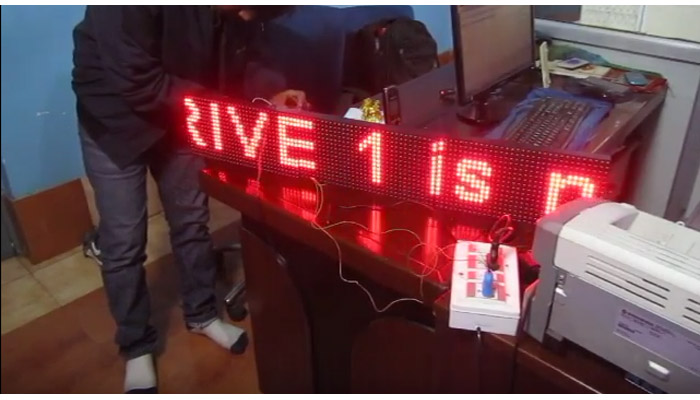
Making LED displays and signage is a complete industry in itself serving all sorts of clients like banks, railway stations, factories, airport and more. In earlier days display units were made using individual LEDs carefully placed and soldered to make matrix of display. But this task was very mundane and slight misplacement of LED gave a ugly look to the board and chances of failure were also high. But now a days ready made panels are available that has 512 LEDs arranged in a rectangle of 32x16 matrix. They are low cost and easily available. Thanks to such LED panels making LED displays are now lot easier. Below I am introducing such a LED display panel.
P10 LED Panel 32x16 Matrix


As you can see in the image above the module has a 16 pin header that is used to connect it to the controller board. The board also has a power input terminal that should be given a 5v DC input that can source upto 3A current. The output header is used to connect more P10 panels to make a larger display.
PIN Description of P10 LED Display
This LED display module has a 16 pin FRC box header for interface. Pin configuration is shown below.

As you can see most of the pins are ground. And that should really make you happy that this display is so simple!
- EN (Enable) is used for PWM brightness control of the entire panel. That means the MCU can control the brightness by feeding a pulse width modulated signal on this pin.
- A & B are the multiplex select pins. They take binary input to select any one of the four multiplex rows.
- Shift clock, Store clock and Data are the normal shift register control pins. The shift register IC used is IC74HC595
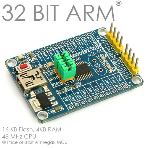
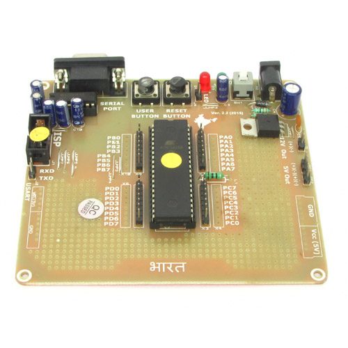
Connection with ATmega8
We have chosen a basic AVR ATmega8 development board to do this experiment. AVR development board has all i/o pins of microcontroller available in male headers making it very easy to hook up p10 led panel to it using female to female wire.
| P10 Display | Dev Board |
|---|---|
| GND | GND |
| EN | PB0 |
| A | PD6 |
| B | PD7 |
| Shift Clock | PD4 |
| Store Clock | PD5 |
| Data | PD3 |
I have highlighted the pins used to interface in the image below so that you do not have trouble locating them.


Download the hex file of this project and burn to the development board using a USB AVR Programmer and power up the system to view the display in action! I have also attached C source of the project so that you can have a look how the programming is done.
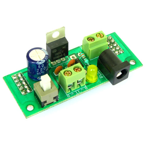
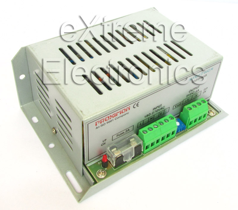
Compatible Power Supply
The power supply shown below can easily supply current strong enough to run 3 to 4 P10 displays.
We cordially thanks the following peoples who shared this page on various social networks and insprided us to develop more quality contents!
Jala, Ernst , My Name Is Omar , Iam A Software, Omar, Mehran Solhjou, Avinash, Gi Tae, Prodip, Marlen Cuevas, Robi, Joven, Arvindkumargaur, Kenrick Hall, Murdani, Natalia Tito, Ihsan, Subroto Ghosh, Santiago Solano , RAMIRO FRANZ, P.sankar, John, Xirox, Shashank, DAVID FLORES, Epy,