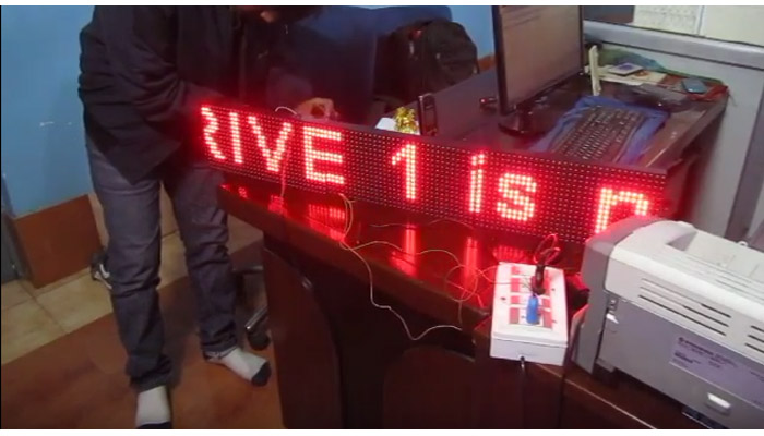
Room temperature display on big screen is a common requirement from industrial sector. Used in server rooms, PLC rooms, storage rooms and many other places in an industrial units. Traditionally seven segment displays of big size (say four inch height) were used. But now a days DMD (dot matrix display) have become so cheap and easily available that we are tempted to use them in place of old seven segment displays. Following are the obvious advantages that immediately comes to our mind.
- Nicer, fancier and advanced look!
- Less wiring
- Less external components required like ULN IC and transistor.
- Gets ready in lesser time.
- Does not cost too much extra money
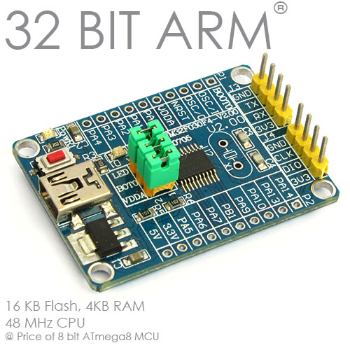
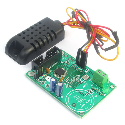
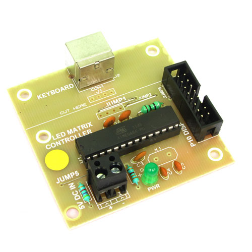
Today I will share circuit diagram and program for such an application so that all my readers can make such a display themselves over a weekend. I will use a common P10 32x16 DMD panel to show the temperature. The microcontroller would be my fav ATmega8 which is a 28 PIN DIP packaged MCU available at low cost. Temperature would be sensed by the popular LM35 sensor using the inbuilt ADC of ATmega8.

Schematic

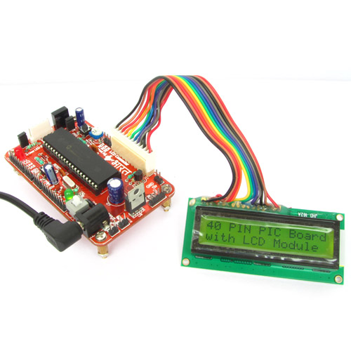
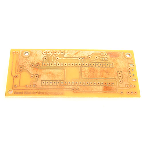
You can design the circuit on any general purpose PCB or a PCB dedicated to ATmega8.
The latter option is easier, cleaner, quicker as less wiring is
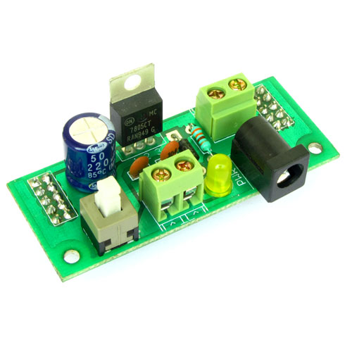
required. Please notice that we have not used any kind of voltage
regulator IC like 7805 in the above circuit, this is because we will
use a 5V 6A SMPS to power the system. A 7805 IC can only provide 1A
current that is NOT enough to drive P10 DMDs.
| S.No | Reference | Value | Part | Quantity |
|---|---|---|---|---|
| 1. | R1 | 4K7 | Resister 1/4 watt | 1 |
| 2. | C1,C2,C3 | 100nF | Ceramic Capacitor | 3 |
| 3. | L1 | 10uH | Inductor | 1 |
| 4. | U1 | ATmega8 | Microcontroller | 1 |
| 5. | U2 | LM35 | IC Temperature Sensor | 1 |
| 6. | X2 | 16 Pin FRC Box Header | 1 | |
| 7. | 16 Pin FRC Cable | 1 | ||
| 8. | P10 Display | 1 | ||
| 9. | 5V 6Amp SMPS | 1 | ||
| 10. | 28 Pin IC Socket | 1 |
P10 LED Panel 32x16 Matrix


As you can see in the image above the module has a 16 pin header that is used to connect it to the controller board. The board also has a power input terminal that should be given a 5v DC input that can source upto 3A current. The output header is used to connect more P10 panels to make a larger display.
PIN Description of P10 LED Display
This LED display module has a 16 pin FRC box header for interface. Pin configuration is shown below.

As you can see most of the pins are ground. And that should really make you happy that this display is so simple!
MCU Configuration
The ATmega8 must be configured to run at internal 8MHz RC oscillator. This step is very vital as the default configuration is 1MHz internal RC. At 1MHz you will notice too much flicker.

We cordially thanks the following peoples who shared this page on various social networks and insprided us to develop more quality contents!
Prodip, Udomsak, My Name Alal Ahamed Hridoy, Hasan, Jimmy, Swapan, Kishore Bhadra, Imran, Ragab Ali, Wito, SOUMITRA MANDAL, Digital_098, Fumu Anne, Nazrul, Horace P. McTitties, ErdoÄŸan, Delwar, Vijayaraj, Sumon, Jagjit Singh, Murdani, Avinash Gupta, Sukhdeo Singh, Avinash,