In the last article I discussed about the general purpose PCBs which helps us build prototypes of our circuits. In this article I will introduce you to one more prototyping tool, the breadboard. A bread board offers more flexibility while prototyping. In general purpose PCB, components are placed then soldered, this makes them permanent on their position. But during testing this much rigidness is often very irritating. For example in a case where you made some mistake or just want to make any improvement to the circuit. In the both the case some change is required but due to permanent nature, change is very difficult.
Here comes breadboards for our rescue! They are part of very advance method of building test circuit. They don't use soldering method and due to this some times they are called a solderless breadboard. Ability to make circuits without soldering is also useful for beginners who don't know how to solder or yet they have not mastered the art of soldering. They are most useful for kids, because sometimes we don't want them to be playing with a hot soldering iron.
A commonly used breadboard is shown below.

A Breadboard
It has ten rows (lines) of holes in the main area. Each line has 64 holes. Their are also two power lines at the top and two at the bottom.

Power lines and main area
To fix a component on the breadboard you just need to insert the legs of the component in the hole, thats it ! It will hold it securely and at the same time make an electrical connection with it too.

A resistor fixed on a breadboard
Now let us understand how the holes of the breadboard are grouped and internally connected (electrically).
Power Lines
Since all electronic circuit requires power to function, therefore the power lines are important part. There are two power lines at the top, all holes in a line are connected horizontally. But their is a break at the exact center of the board.

Power lines
In most circuits only one of top and one of the bottom power lines are used. We connect the power output from a battery or an adapter to these lines, and this voltage is available through out the length of bread board.
Warning! As told above that there is a break in the power rail at the midways, so you need to use a hookup wire to bridge the gap if you wish the voltage to be available through out the length.
Two of these lines are provided on each side because some circuit requires two different voltages to work. For example some part of the circuit needs 5v while some parts need 12v. So in this case we can apply 12v input to the first of the top power line and 5v to the second.
Similar to the top two power lines there are two bottom power lines too. They are generally connected to the negative terminal of the battery or the adapter. This line is called the ground or the common.
Main Area
The main area is where all the components of a circuit design are actually placed. This area is also divided in two parts, top and bottom. Both the area has 64 columns (vertical lines) and in each column their are five holes. All these five holes are connected internally.

Main area
Working with Breadboards
ICs (Integrated Circuits) chips in DIP packages are placed at the exact center (vertically) on the bread board such that the half of legs on one side is inserted in the holes of top main area and the other half legs are inserted in the holes of bottom main area. This way the pins on the opposite sides of the IC do not get short circuited with each other as their is a break at the exact center of the bread board.

Placing ICs
Interconnection
Interconnections between components are made using single strand wires.

Single Strand Wires

On left, a small piece of wire cut and some length of insulator removed from both the sides.
On right, pin 5 on the IC connected to the ground supply line.

Complete circuit built on a breadboard.
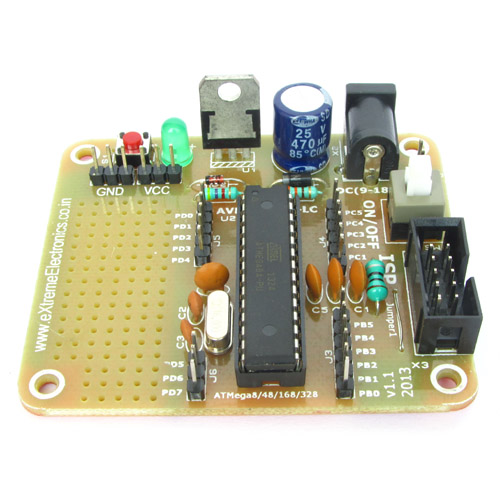
Breadboard Power Supply System
Microcontroller based projects requires a regulated power supply. This regulated supply is made using regulator chips like 7805. Since this regulator circuit will be required in all projects, it is wise not to make it everytime due to following reasons
- To save space on breadboard.
- To save time.
It is available readymade as show in the image below. Just plug it in your breadboard and the power supply part is done in no time !

Breadboard Power Supply
Features
- Power input via standard DC Socket, so you can use adapters without any mess.
- Input can also be provided through wires, you need to connect them to the green screw terminals.
- On/off switch.
- Power indicator LED.

We cordially thanks the following peoples who shared this page on various social networks and insprided us to develop more quality contents!
Nguyen Minh Anh, Kolj,