Resistors are one of the most basic electronic component. They opposes(or resists) the flow of electric current through them, that is why they are named resistors. They are used to control the electric current in a circuit. Fixed resistors are two terminal devices. That means they have two connecting leads or legs.
The resistor's ability to reduce the current is called resistance and is measured in units of ohms (symbol: ?).
How resistors look like?
Primarily, resistors (like other electronic parts) can be divided into two types depending on the way they are mounted on PCBs.
- Through hole type (bigger, but easier for prototype assembly)
- Surface mount type (SMT, smaller, good for mass production)
in this article we will cover only the through hole type.
OK, so now let's see how do they look like. Since the look depends on type and specification, it is not possible to provide a single image. But we have tried to collect the all common types.
 |
| Fig. Resistors of various power ratings |
From the image above you can notice the following.
- Resistors have two leads made of metal.
- They have cylindrical shaped body. (only if power rating is less than 5W)
- They have bands of colour marked on their body.(only if power rating is less than 5W)
- Their size increases with the amount of power they can dissipate.
The value of resistor (i.e. the resistance they provide) is marked by using a colour code on their body.
Measuring the value of a Resistor
A DMM (Digital Multimeter) can be used to easily measure the value of a resistor. Most DMM have a mode selection rotary switch as shown in the image below. The rotary switch should first be set on the ohm mode.
 |
| Fig. Digital Multimeter |
The resistance measurement mode of rotary switch is marked by a ohm symbol as shown in the image above. The ohm mode is further split into several range of resistance. For example 200 ohm range can measure resistance up to 200 ohms. If the sample of resistor being measured has resistance greater than 200 ohms, the screen of DMM will show 1. This means out of range. So now you have to put the rotary switch to next higher range i.e. 2000 ohm. If the resistance is i the range of measurement, it will be shown on screen.
 |
| Fig. Measuring a Resistor |
Soldering Resistors
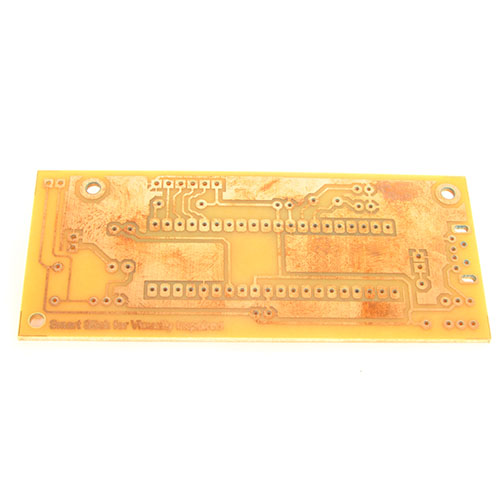
On a printed circuit board, an outline pattern is drawn to help you correctly mount the resistors. See the image shown below
 |
| Fig. PCB land pattern for resistor. |
As it is clear from the image that it has two holes on the either sides to insert the legs of resistor. The legs of the resistor are bent at 90 degrees and inserted into the PCB holes. Then they are soldered on the other sides to make their legs connected with the circuit. Finally excess part of the metallic legs are cut off by a nipper.
 |
| Fig. Mounting resistors |
NOTE: Their is no need to mount resistor in any specific orientation. That means any of the two leads can be inserted into any of the two holes.
Schematic Symbol for Resistors
Their are two types of symbol widely used to represent a resistor in an electronic schematic (circuit diagram).
 |
| Fig. Resistor Symbol |
- A : Is the symbol of resistor as per the IEC standard.
- B: Is the American style symbol, also according to the IEEE standards.
We cordially thanks the following peoples who shared this page on various social networks and insprided us to develop more quality contents!
, Chucksman, Dheeraj, θεοδωÏοσ,