Token systems are used to manage queues of people in banks, hospitals and other places. Visitors are allotted serial token numbers and have to wait till there number is called. To call the token number the employee of the organisation is provided with a handset, using it she can type in a token number and then press the send button. This sends data over wireless channel to the remote display which shows the number and also play a sound.

In this article I will describe how you can make such a system using AVR ATmega8 microcontroller. First I will start with the table unit, i.e. the transmitter part. The transmitter part has four major parts.
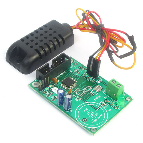
- The ATmega8 microcontroller
- 3x4 matrix keypad
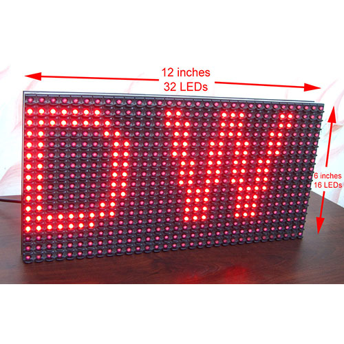
- 3 digit seven segment display
- 433 MHz ASK RF Transmitter
The keypad is used to enter the number, the three 3 digit display show the entered number. The ATmega8 is clocked from the internal 8MHz oscillator so we do not need to attach any external crystal in this project. This selection of internal 8MHz oscillator is done by programming the fuse bits with required values. This value can be calculated by consulting the datasheet of ATmega8.
The circuit diagram for the token display transmitter unit

Matrix Keypad, its pin configuration and connection
I am giving some information that will help user correctly connect the matrix keypad.

A 3x4 matrix keypad has three columns of buttons named C1,C2,C3 or four rows of buttons named R1 to R4.
| Key Pad | ATmega8 |
|---|---|
| Row 0 | PC0 (PIN 23) |
| Row 1 | PC1 (PIN 24) |
| Row 2 | PC2 (PIN 25) |
| Row 3 | PC3 (PIN 26) |
| Column 0 | PC4 (PIN 27) |
| Column 1 | PC5 (PIN 28) |
| Column 2 | PB5 (PIN 19) |
Multiplexed wiring of three seven segment displays
The three display modules should be wired in a multiplexed manner to make a three digit display. In this wiring pin 'a' or all three displays are connected together, similarly all b's, c's and so on. So you are left with seven outputs from a to g which will be connected to the MCU ATmegs8. The the common pin (com) of each display are driven through a BC548 transistor.


This multiplexed wiring can be quite challenging as it requires lots of wirings! You can use this PCB to speed up! I have also used it to make the prototype. Please note that all displays are common cathode type. This three digit display will show the typed characters locally on the table unit.
We cordially thanks the following peoples who shared this page on various social networks and insprided us to develop more quality contents!
Celal, Sanjay Karmkar, Murugan, Jaime, Ram, Uttam Dutta, Zafar Ahmed Abbasi, Zafar, Colin , Rayhan, Rally, Pramod, Bijujp, Nisar, Satyam, Elaiya, , Appalaraju, Saket, GaneSh Gupta, Sonu Kumar, Sonu Kumsr, Vaishali, Aji Ahamed, Ramesh,