In the last article we have discussed the handset unit for token number display system. Using this handset unit, a person can type a number which will then be displayed in the main display unit. This unit will be discussed in this part.
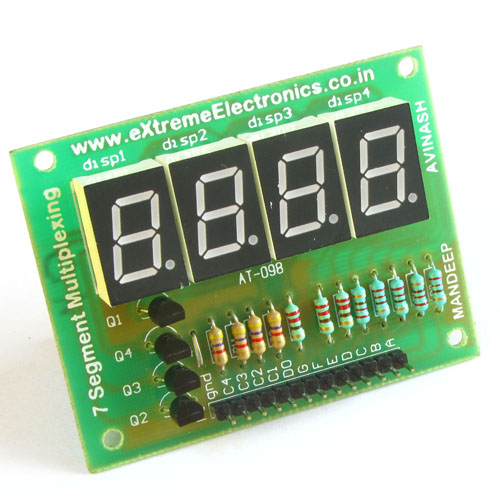
The main display is made using four inch LED displays. Three such display modules are used. These are common anode type.

The names of the segments are shown in the image below.

The three displays are wired in multiplexed manner, in this wiring arrangement the A segments of all three displays are connected together and then finally to the i/o pin of microcontroller. In the same manner all B,C,D,E,F,G segments are connected.

How these segments (i.e. A,B,C etc) are connected to the ATmega8 AVR MCU is detailed in the table below :-
| Display | ATmega8 |
|---|---|
| A | PD6 |
| B | PD5 |
| C | PD4 |
| D | PD3 |
| E | PD2 |
| F | PD1 |
| G | PC0 |
These are not connected directly to the MCU's i/o pin, but through a ULN2003 driver IC as the display needs more current than MCU can supply.
Now comes the wiring of the common pins, these displays need 12v to glow, but the ATmega8 and other MCUs run at 5v maximum. For this we need special arrangement of the transistors to make this switching circuit.

We need three such drivers to control the 3 digits. We number the three digits, the left most is number 3, the middle one is 2 and the right most is number 1. These digits are driven by ATmega8 i/o pins PB0,PB1,PB2.
We cordially thanks the following peoples who shared this page on various social networks and insprided us to develop more quality contents!
Mehmood Ul Haq, Abdull Aleem, Imranbutt, Janani,