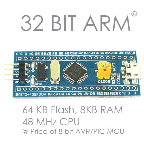
In this tutorial I will teach you how to program STM32F0 series of ARM Cortex M0 based 32 bit microcontrollers using ST-LINK. The ARM Cortex M0 core was designed to replace the older 8 and 16 bit MCUs (like AVR,8051 and PIC) with a much faster and advance microcontroller that meets modern day requirements. Due to this reason Cortex M0 based MCUs have lower pin count like 20, 32, 48 etc like those of 8 bit microcontrollers. So these microcontroller chips uses an interface named SWD for programming and debugging. The SWD interface needs only two lines for communication between the microcontroller and debugger/programmer hardware. SWD stands for serial wire debug.
Here by the word "programming" I mean transferring a program developed in a PC to the memory of the microcontroller chip. This is the final step in the software development cycle of microcontrollers. You may have hired some one who have developed and tested the program for you and have finally handed over you the program in form of files which you have kept in your PC. Now the time has come to "burn" that program to the microcontroller chip that will be installed in your final hardware product.
You cannot connect your microcontroller directly to your personal desktop or laptop computer. For that you need a mediator device called a programmer (the same device is also used for debugging so also called a debugger). Once such programmer I recommend is the ST-LINK. It is available at a very low cost and works great! The ST-LINK is USB based programmer thus it connects to the USB port of your computer. Your microcontroller (or the development board which has the microcontroller) can be connected to the other end of ST-LINK dongle.

One end of the ST-LINK that connects to your PC does NOT need much introduction and you can easily plug it in a free USB port! Now come to the other end, it has a 10 pin (5x2) male connector and name of each pin is clearly printed on the body. We won't be drawing any power from this dongle to power our development board. To the bottom 4 pins labelled 3.3v and 5.0v are useless to us. Only pins of our interest are :-
- SWDIO
- SWCLK
- GND
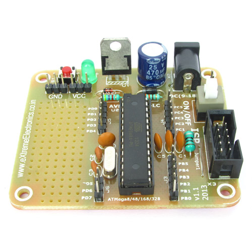
Our development board also have pins dedicated for program uploading, these are shown in the image below.


Connect them to ST-LINK a shown below. Connections can be done using three pieces of single pin female to female wires. This wire is supplied with ST-LINK package.
- GND->GND
- CLK->SWCLK
- DIO->SWDIO
That's it! Now you are ready to burn your very first program to 32 bit ARM MCU! In the last tutorials I have already discussed the installation of KEIL uVision IDE and how to compile a source program using it. Now we learn how to use KEIL uVision IDE to transfer program to the microcontroller chip using ST-LINK dongle.
ST-LINK Driver Installation
The ST-Link is a USB device that you can plug into your PC easily, but in order for your PC to detect it properly you need to install the drivers. This step should be done before plugging the dongle in USB port. Follow this step carefully to avoid problems in the future.
The driver for ST-LINK can be downloaded from the link below.
Before starting the installation login to Windows using admin account. This step is very important. Unzip(extract) the file somewhere in your hard disk. This step depends on which unzip software you are using. Run the file dpinst_amd64.exe and follow the step. If you get error running this file, then instead of this file run dpinst_x86.exe
Follow the steps of the installer wizard. For any permission prompts choose Yes.


I have attached a sample project that you can open in KEIL MDK, compile it using the F7 key and burn it to the microcontroller using F8 key. Keil MDK supports a variety of programmers so first you need to tell it that you are using ST-LINK. Goto Project > Options for target menu item.

This will open a dialog like this. Goto the Debug tab and select ST-Link Debugger.

Now every thing is setup, programming the chip is now a matter of just hitting the F8 key!

You can also use the menu Flash > Download command for the same purpose in place of F8 key.

After flashing (programming) is successfully over, you need to press the RESET button on development board in order to start the program. This program blinks the LED present on the development board.
I have two versions of the program one for STM32F030F4 development board and one for STM32F051C8 board. The first board is based on a 20 PIN chip while the latter is based on a 48 PIN chip. You must have both of these development boards if you want seriously learn 32 bit ARM programming and replace your poor old AVR, PIC and 8051 MCU.
We cordially thanks the following peoples who shared this page on various social networks and insprided us to develop more quality contents!
Avinash Ofc PC,