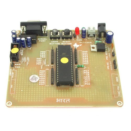
In this tutorial we will discuss the interfacing of the relay board with 40 PIN AVR Development Board. They are connected according to the table given below.
| Relay Board | Development Board |
|---|---|
| V | 12V |
| S | PB0 |
| G | GND |
Location of the pins on the development board is shown in the image below.

Pins from development boards are connected to the relay board using the single pin female to female burg wires.

They have female connectors at both the ends and thus fits easily on the male headers of the development board and the relay board.

We cordially thanks the following peoples who shared this page on various social networks and insprided us to develop more quality contents!
Akshay, Jayesh Gohil, Danghoa, Kuldeep, Harmony,